Clever reset solution and more
Hello! Since this blog was created a few months ago it's been completely void of any content. To mitigate this I thought I'll kick things off with rehashing one of my old articles, originally written for Hot-Style #7, a polish C64 diskmag, which I recommend to check for yourself: https://csdb.dk/release/?id=206132
Anyways, enjoy the first article, more to follow soon :) (or in a couple of months, we'll see ;) )
The C64 users always had an inconvenient little problem with the machine – lack of convenient reset button. They devised a lot of different minor and major modifications to solve that problem. There’s a lot to say about all of them, but one has speciffically caught my attention and I decided to apply it in my own modded C64C.
I’m talking about a small project, that I’ve found while browsing through C64 websites. It’s author cleverly used a cheap and highly available Atmega microcontroler circuit – Arduino Pro Mini.
Original article can be located here: http://www.breadbox64.com/blog/switchless-reset-mod/, but I’ll describe a version that I’ve updated with a few minor tweaks.
The concept is simple, we upload a program into the circuit, which based on input signals (in this case the RESTORE button press) controls the signals sent to Commodore`s motherboard resulting in warm or cold reset and state changing on an address line of optionally installed EEPROM memory.
Beware! Before you grab a soldering iron and happily decide to install the modification in your favourite C64 remember, that any hardware alteration can lead to unintended damage.
What will be required for this project?
A USB capable PC, which will run the official Arduino toolkit (https://www.arduino.cc/). Of course the Arduino Pro Mini circuit is the key element of this project. When purchasing, take care to select the correct version. There are two variants, one runs on 5V and the other on 3.3V. Since the Commodore 64 also uses 5V, it’s necessary to choose that version.
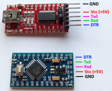
To be able to program the circuit we’ll also need an USB to RS232 adapter (don’t confuse one with UART programmer, which looks almost identically). I recommend FDTI232 programmers, which work without a hitch on the latest OS’es and are also equipped with DTR output, allowing automatically reset the Arduino before programming begins. Unfortunately most of available tutorials fail to mention that and asks the user to manually press reset button in a very speciffic moment, which is very tedious and can cause a rageous reaction, when you’re attempting to sync it correctly for the twentieth time.
Aside those two devices we’ll also need 5 or 6 wires to connect all the necessary signals, depending on if we also want to use the rom selector.
Programming the Arduino
After installing the toolkit and adapter driver, start up the Arduino IDE and paste in the code listing attached with this article.
Now let’s connect the Arduino Pro Mini in a following fashion:
- ground on the adapter to ground of Arduino,
- Vcc on the adapter to Vcc on Arduino,
- Rx on the adapter to Tx on Arduino,
- Tx on the adapter to Rx on Arduino,
- DTR on the adapter to DTR or Reset on Arduino.
Next select propper circuit board from the menu Tools > Circuit board… > Arduino Pro or Pro Mini. The processor we’re using Tools > Processor… > Atmega 328p (5V, 16MHz) and the adapter Tools > Programmer > AVRISP mk II.
If everything was configured and connected correctly, after pressing Upload button, the Arduino should blink it’s diodes a few times and the IDE will notify us that the upload was successful. If any error occurs, make sure all the steps up to now were done correctly.
Installation
Now it’s time to proceed with the hardware part of the solution. We have to connect the board accoarding to the following scheme:
- Vcc on Arduino to +5V line on the C64 motherboard,
- GND on Arduino to GND on the C64 motherboard,
- A0 analog I/O line to RESTORE button line on the C64 motherboard,
- digital I/O line 3 to CPU Reset line on the C64 motherboard,
- digital I/O line 4 to /EXROM line on the C64 motherboard,
- digital I/O line 5 to leg 27 of the EEPROM memory (optionally).
Sounds complicated? Unfortunatelly that’s the hardest part of the whole mod and because a lot of different versions of the C64 motherboard exsist, it’s very probable that you’ll need some aid from the service manual to find where exactly are all the signals on the one you have.
Anyway, for now we’ll use a popular C64C motherboard variant as an example – Assy No. 250469 Rev. B.
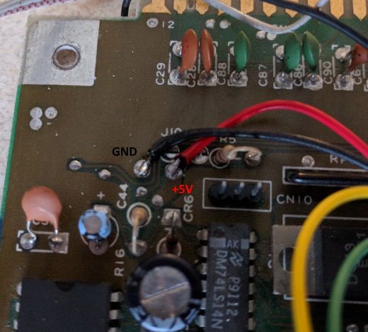
First we need to supply 5V to the circuitboard, which we’ll find in a lot of places all over the C64 board. I went with a comfortable location right beside the POWER LED pins. Looking at the motherboard from the usual spot we take when we use the Commodore, +5V can be located on the first free soldering point on the left of the LED pins. In the same line just beside there’s also a point with ground. It’s worth to make sure and confirm the correct values with a Voltometer.
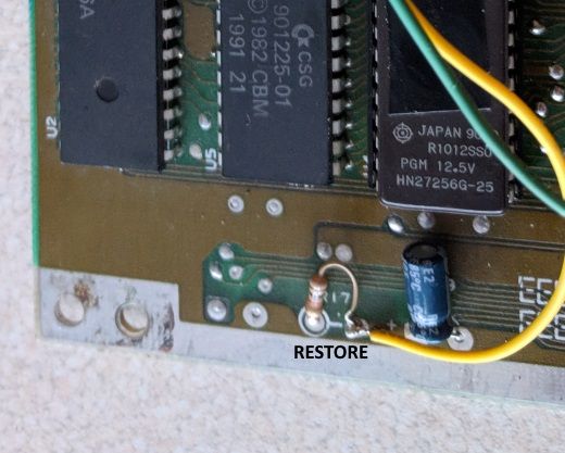
The RESTORE signal is also relatively easy to find on this motherboard. We’ll locate it almost at the bottom edge of the board, on one of the R17 resistor legs (the one near the neighbouring capacitor). Why use the RESTORE button? Because it’s the only one that’s has a direct connection on the motherboard and isn’t in any way coded.
The RESET line can be located on the anode of CR5 diode, which you’ll find just above the character ROM. Unfortunately it’s difficult to solder a wire in from the upper side of the board, which gives us two options, either to move the diode, or to solder the wire from the backside, which I did.
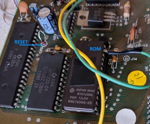
The most difficult to locate for me was the /EXROM line. On my motherboard the soldering point was covered up by a sticker. Also near the bottom edge between PLA and the VIC-II chips you’ll find five soldering points in a row. Counting from the left, the fourth one is the /EXROM line.
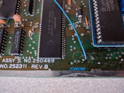
If your C64 is also equipped with a dual ROM, it’s possible to connect one of it’s legs to the I/O line 5. The attached code allows to switch between two ROM locations, but it’s possible to add in support for four. Keep also in mind that in the old C64 models Basic and Kernal were located in separate ROM chips, unlike the C64C where they only use one.
If everything was connected correctly, you can test the solution.
How does it work?
The mod adds a few functions to our C64, depending on how long we’ll press the RESTORE button. Pressing it for two to four seconds, executes a so called warm reset, which starts the Basic setup routine and redraws the screen. If that’s not sufficient, because let’s say part of the memory was overwritten by users code, it’s possible to do a longer, four to seven seconds press and execute a cold reset instead. This takes the Commodore through the complete startup routine and works in a same fashion as a reset button on a cartridge. If the computer has the dual ROM installed and connected, it’s also possible to press RESTORE for seven to ten seconds and this in turn will do a cold reset and additionally switch the currently used ROM location.
For cartridge compatibility purposes I’ve also added the ability to start up the machine using the second ROM, by pressing the RESTORE button during the power on.
And voila! This way we’ve supplied our good old C64 with a neat CTRL+ALT+DELETE equivalent without drilling any holes or damaging the housing. To make the solution more elegant and easier to dismount it’s possible to use goldpin connector instead of directly soldering in the wires.